 ←This is the front view. It shows the aluminum chassis (0.125" thick) and the controls for the soundcard section. I know it's kind of ugly, but it serves its purpose. This soundcard includes 2 Neutrik combo connectors (for both 1/4" TSR and XLR microphone inputs), a 48V phantom power switch, level controls and LED meters. There's also a basic momentary pushbutton for the amplifier modules on the far right.
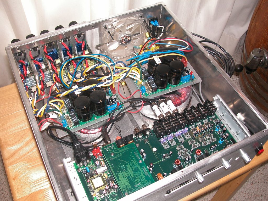
→With the cover off, you can see the internal components. The soundcard is near the front (bottom of the pic), the toroids and power supplies are in the middle, and the amp modules are mounted on the back. The amps for the 3 front channels are rated at 400W into 4Ω loads, while the 2 rear channels use amps rated at 180W into 4Ω loads. Since these amps have different operating voltages, we needed 2 toroids and power supplies.
 ←This picture shows a rear view of the prototype. The amp modules are attached to 1-1/2"x6"x1/4" bars of aluminum, which serve as additional heat sinks. We are using Cardas patented binding posts for the speaker connections. We've also used a quiet (and slow) 120mm fan to pull heat out of the interior space. After testing, we've discovered that the amps run pretty cool and some of our efforts to dissipate heat might be overkill. A little over-engineering can't hurt.
Click on the pictures to get a larger view.

No comments:
Post a Comment